

In today’s data-driven world, the reliability of your network infrastructure is paramount. While Wi-Fi is convenient, nothing beats the speed, security, and stability of a wired connection, especially in environments with high electronic interference. This is where Shielded Category 6 (Cat6) cable shines. However, its superior performance is entirely dependent on one critical factor: a perfect termination.
As specialists in high-performance custom cable assemblies and wire harnesses for industrial, medical, and automotive applications, we at Dlay Cable understand that precision is not optional. A poor termination can negate all the benefits of a high-quality shielded cable. dlaycable provides a detailed, professional walkthrough to ensure every connection you make is robust, reliable, and ready to perform.
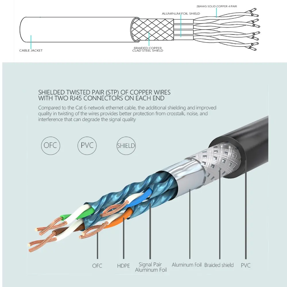
Why Proper Shielded Termination Matters
Unlike standard Unshielded Twisted Pair (UTP) cable, Shielded Twisted Pair (STP) Cat6 includes an outer conductive shield—typically a foil wrap, a braided metal mesh, or both. This shield is its key advantage, designed to protect the data-carrying conductors from electromagnetic interference (EMI) and radio frequency interference (RFI). This “noise” is common in environments with motors, power lines, fluorescent lights, and other industrial machinery.
A proper termination does two things:
- Ensures Data Integrity: It correctly aligns the eight conductors for flawless data transmission.
- Completes the Shield: It connects the cable’s shield to the shielded RJ45 connector, allowing any captured interference to be safely diverted to ground. Without this, the shield is useless and can even act as an antenna, making performance worse than an unshielded cable.
Gearing Up: Essential Tools & Materials
Working with professional-grade components demands the right tools. Using inadequate tools is a primary cause of termination failure. Before you begin, gather the following:
- High-Quality Shielded Cat6 Cable: The foundation of your connection. The quality of the copper and shielding directly impacts performance.
- Shielded Cat6 RJ45 Connectors: These feature a metal housing that is essential for grounding the cable’s shield. Ensure they are rated for the specific cable you are using (solid or stranded core, and correct conductor gauge). Many come with a “load bar” to simplify wire alignment.
- Cable Strain Relief Boots: Protects the locking tab and prevents the cable from kinking at the connector.
- RJ45 Crimping Tool for Shielded Connectors: A critical tool. It must be designed to not only crimp the pins but also to secure the metal housing of the shielded connector around the cable’s shield.
- Cable Stripping Tool: A dedicated cable stripper is better than a knife, as it helps prevent nicking the internal conductors or the shield.
- Flush Cutters: For a clean, flat cut of the conductors.
- Cable Tester: A non-negotiable final step. A good tester will verify pinout, continuity, and the integrity of the shield connection.
The Step-by-Step Termination Process (T568B Standard)
We will use the T568B wiring standard, as it is the most common in commercial and residential networks in North America. For a connection to work, both ends of the cable must be terminated to the same standard.
Step 1: Preparation and Jacket Removal
First, slide the strain relief boot onto the cable. Don’t forget this step, as you can’t add it later! Next, carefully strip about 1.5 inches (40mm) of the outer jacket from the end of the cable. Be very careful not to cut through the metal shield underneath. Inspect the shield and conductors for any nicks; if you find any, cut the cable and start again.
Step 2: Managing the Shield and Drain Wire
You will now see the foil and/or braided shield. Find the thin, uninsulated wire running alongside the shield—this is the drain wire. Its job is to ground the shield.
Carefully fold the braided shield back over the cable jacket. If there is a foil shield, you can either trim it away or fold it back with the braid. Wrap the drain wire around the folded-back shield. This combined shielding will make direct contact with the metal housing of the RJ45 connector when crimped, creating the ground path.
Step 3: Exposing and Arranging the Conductors
Cut away the central plastic spline (if present) that separates the pairs. Untwist the four pairs of wires and straighten them out as much as possible. Now, arrange them in the T568B color code sequence from left to right:
T568B Order (Left to Right):
- Orange/White
- Orange
- Green/White
- Blue
- Blue/White
- Green
- Brown/White
- Brown
Flatten and align the wires, holding them tightly together. Using your flush cutters, trim the wires so they are a uniform length, leaving about 0.5 inches (12-14mm) exposed from the jacket.
Step 4: Inserting Wires into the Connector
If your connector uses a load bar, carefully thread the arranged wires through it according to the color code. This makes insertion much easier. If not, proceed without it.
Hold the RJ45 connector with the locking tab facing down and the metal housing facing you. Carefully slide the aligned wires into the connector, ensuring they stay in the correct order. Push firmly until each wire reaches the end of its channel and is visible at the front of the plug. The cable jacket should be pushed inside the rear of the connector as far as possible to be secured by the crimp.
Step 5: Crimping for a Secure Connection
Insert the connector into the appropriate slot on your shielded crimping tool. Squeeze the handle firmly and fully. This action does three things simultaneously:
- Pushes the pins through the insulation to make contact with the copper conductors.
- Secures the cable jacket with a plastic strain latch.
- Crimpages the metal housing of the connector down onto the cable’s shield and drain wire, completing the ground.
Once crimped, slide the strain relief boot up and over the back of the connector.
Common Pitfalls and How to Avoid Them
- Mistake: Using UTP connectors on STP cable. Solution: Always use shielded connectors with a metal housing to properly ground the shield.
- Mistake: Untwisting too much of the wire pairs. Solution: Keep the untwisted portion as short as possible (under 0.5 inches) to minimize crosstalk and interference.
- Mistake: The jacket is not inserted far enough into the connector. Solution: Ensure the jacket is securely held by the connector’s strain latch after crimping to prevent wires from pulling out.
- Mistake: Incorrectly handling the drain wire. Solution: The drain wire MUST make solid contact with the connector’s metal housing. Wrapping it around the shield before crimping is the best practice.
The Final Check: Always Test Your Connection
Never assume a termination is good based on visual inspection alone. Use a quality network cable tester to check each pin connection. A good tester will confirm continuity for all eight wires and, crucially, verify the integrity of the shield (ground) connection from end to end. A “pass” on the tester is the only true confirmation of a successful termination.
Your Partner in Connectivity
Mastering the termination of shielded Cat6 cable is a skill that ensures the highest level of network performance and reliability. It protects your critical systems from the disruptive effects of EMI and RFI. At Dlay Cable, we live by these standards of precision and quality every day.
Whether you require expertly pre-terminated custom cable assemblies for a project or need high-performance bulk cable for your own installations, our commitment to quality ensures you have a foundation you can trust. For mission-critical applications where failure is not an option, rely on the experts. Rely on Dlay Cable.